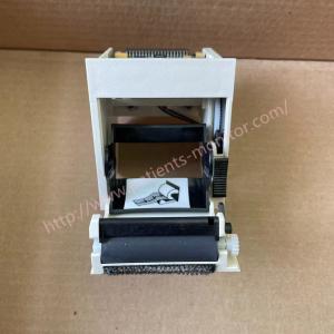
Med-tronic LP20 LP20E Defibrillator Recoder Printer MODEL XL50 PN 600-23003-09 MPCC PN 3200920-000
Printer Module Installation
Warning
Possible blows and damage to equipment. Follow the removal procedure carefully to avoid bumping or damaging the cable during removal.
Note: If you installed only the A12 printer, start with step 9. Follow these steps to install the printer module:
1. Slide the W14 printer flex cable under the W06ECG cable and guide the printer cable along the right side of the holder.
2. Connect the printer cable connector and the 4-pin power cable connector to the large connectors on the monitor.
3.Insert the 2.4 pin plug into the small hole on the shield.
4. Connect the 4-pin power plug to the A03 power module of the J45 and ensure that the plug is seated properly.
5. Place the printer shield (89) in the base box.
6. Install three new 4-40 x 0.312 (173) screws at the bottom of the printer cover.
7. Once removed, press the clip (225) on the printer cover to secure the J45 pigtail.
8. Install the printer panel (83) and make sure it is flush with the bottom.
9. Connect the W14 printer cable to the J1 connector on the printer. The cable should lie flat against the back of the printer.
10. Ensure that the W14 printer flex cable is between the two clamped screws.
11. Slide the A12 printer into the printer cover.
12. Tighten the two clipped screws on the A12 printer.
13. Attach the paper roll to the A12 printer and close the printer cover. 14. Install the plate pack.
14. Install the front cover.
15. Install the top case.
16. Install the A07 battery.
18. Complete Picture in Picture
LIFEPAK 20/20e Defibrillator/Monitor Interconnect Diagram
| Item name | Med-tronic LP20 LP20E defibrillator recoder printer MODEL XL50 PN 600-23003-09 MPCC PN 3200920-000 |
| Brand | Med-tronic |
| Model | 3200920-000 /600-23003-09 |
| Use place | Hospital Devices; Medical Care; ICU; |
| Deliver time | 3-5 days |
| Warranty | 90 days |
Printer Module Removal
WARNING! Possible shock and damage to the device. The cable can be pinched and damaged during disassembly. To avoid the cable getting caught, follow the removal instructions. To remove the A12 printer unit:
Note: Before disassembly, remove the following parts: - A07 battery - Top case - Front case - Stand for boards
1. Open the printer door and remove the roll of paper from the printer.
2. Loosen the two screws attached to the back wall inside the printer.
3. Pull the printer A12 carefully out of the printer compartment (89).
4. Disconnect the printer's W14 flexible cable from the printer to the printer's J1 connector.
Note: If you delete the A12 printer, the deletion process will be complete. If you are removing the printer cover or the W14 printer flex cable, continue with the removal process until the desired part is removed.
5. Slide the edge of the printer (83) up and out of the bottom of the housing.
6. Remove and remove three 4-40 × 0.312 Screws (173) from the bottom of the printer housing (89).
7. Carefully lift the cover to access the 4-pin power cord.
8. Disconnect the 4-pin power cable from power module A03 on J45 and insert it into the small slot in the housing.
9. Thread the 4-pin power cord and flex from the W14 printer through the widest part of the box.
10. Remove the printer housing (89) from the lower housing.
11. Pick up the W06 EKG cable and carefully remove the W14 printer flex cable from the lower compartment. The cable is attached with glue, so remove it evenly to avoid damage to the connector or cable.
Observed Symptom
Not printing
Suggested Corrective Action
Perform printer test.
Check for proper paper.
Check for 3.3 V on pins 14 and 16 on the J38 test connector on the A05 UI PCB.
■ If either is higher than 3.3 V, replace the W14 Printer Flex Cable. ■ If both are lower than 3.3 V:
– Check or replace the A12 Printer Assembly.
– Replace the A05 UI PCB
Light print
Verify use of proper paper.
Check the W14 Printer Flex Cable connection.
Check or replace the A05 UI PCB.
Missing or broken characters
Verify use of proper paper. Clean the printhead. Check or replace the A12 Printer Assembly